
Need to sort your tablet candies by color? This is how to automate the process using Arduino! If you have ever dreamed of having the ability to sort color tablet candies automatically, then this great machine might make your day. But, before you start, you will need to get your hands on some essential components. Inclusive of various drill bits, and other tools, you will also need the following bits and pieces.
Main components:
- 1 no. Arduino Nano.
- 1 no. NEMA 17 Stepper Motor.
- 1 no. TCS2300 Colour sensor.
- 1 no. Micro servo.
- 20×20 Aluminium rod.
- 20×20 Aluminium profile rod.
- 1 no. micro cooling fan.
- 1 no. A4988 Driver module.
- 3mmMDF Board or playboard.
- Plexiglass.
- 4 no. paper cups or similar receptacle.
- 1 no. custom PCB board (or just use a sandwich board and connector wiring).
- Plastic tubing.
- Assorted PCB wire female connectors and male pins.
- A packet of colorful tablet candies like Smarties (sold in the UK only).
- Various 3D printed parts.
- Ancillary components:
- Mathematical compass.
- Protractor.
- T-shaped screw threader, or similar accessory.
- White paint or white paint spray can.
- 1 no. 16 mm spade drill bit.
- Plastic-card or cardboard for assorted components.
- Electrical wires and soldering gear.
- Various 3D printed parts.
- Assorted screws, nuts, and bolts.
Once you’ve collected these together or purchased them in, it is time to crack on and start building your very own Arduino-powered color sorting machine.
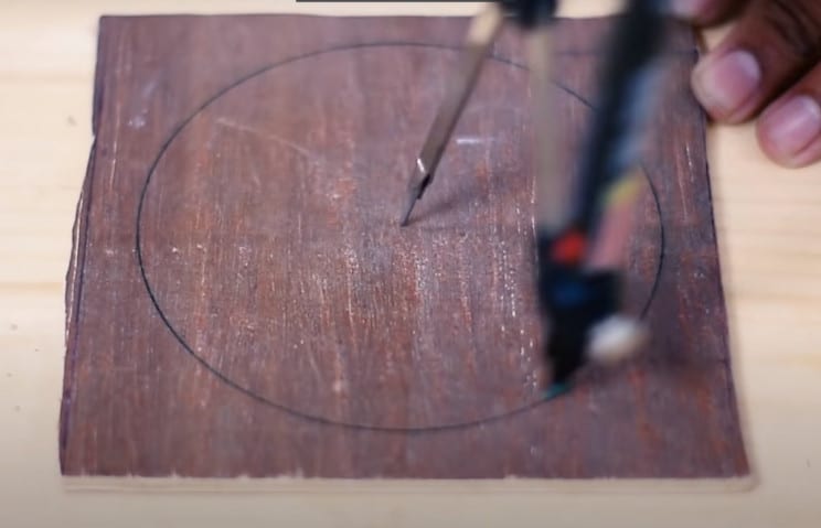
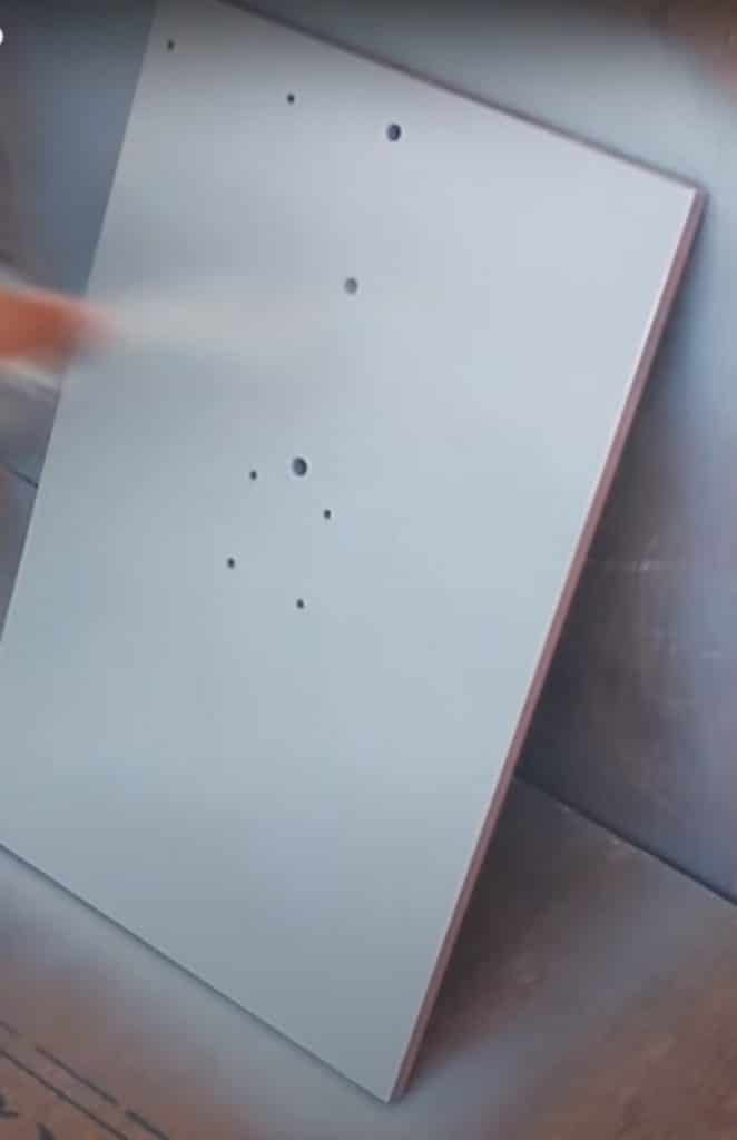
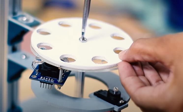
The first step is to take the plywood or MDF board and mark out a 1,9 in (5 cm) radius circle using a pair of compasses. This will form the primary color sorting disk. Now cut out the circle/disk using a mechanical saw or good old fashioned hacksaw. Next, drill a hole right in the center for later mounting to the machine. Using the compass again, mark out a smaller circle about 1,5 in (4 cm) in radius on the board and using a mathematical protractor to mark out eight points each at 45-degree intervals around the circumference of this smaller circle.
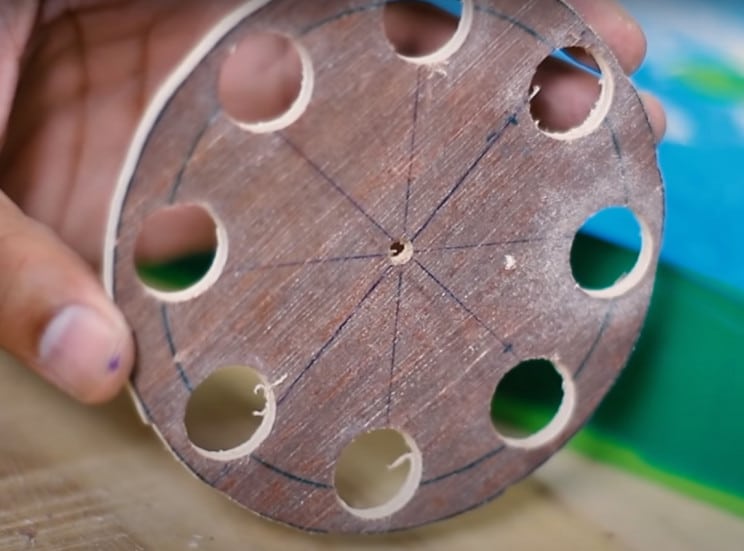
These indicate the position of the color piece receptacles for the color sorting machine disk. Drill a small pilot hole at each of the 45-degree marks on the smaller circle. Using the spade drill bit, expand the holes for the receptacle on the inner circle to fit your chosen color candies. Now, sand down all surfaces of the wheel and holes.
You can use a motorized lathe or simply use sandpaper. Spray or hand paint the wheel white (or whatever color you like). Next, take the aluminum rod and file, or use a milling machine, to flatten both the cut ends, if applicable. Also mill down the rod to make one end thicker than the other, as shown in the instruction video.
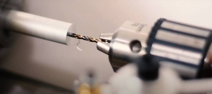
Next, drill a hole in the center to match the diameter of the stepper motor axle — it will be attached to this later. Also, drill a screw thread as required to snuggly fit the stepper motor axle.
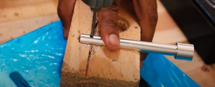
Do the same to the other wider end — as shown in the video. Drill a screw thread into this second drill hole as well. This will need to match the screw size at the center of the previously created perforated disk which will be attached to it. Drill and thread yet another horizontal hole through the other thinner end of the rod; as also shown in the video. Insert a headless screw of the right diameter into the hole as this will be used to attach to the stepper motor axle.
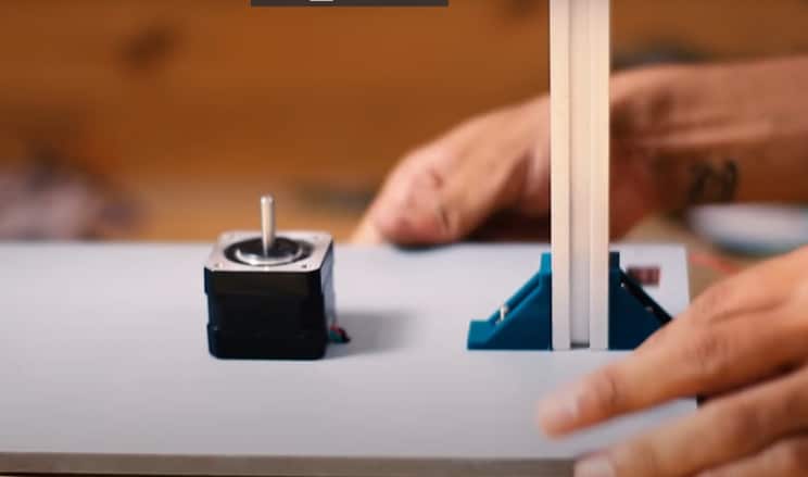
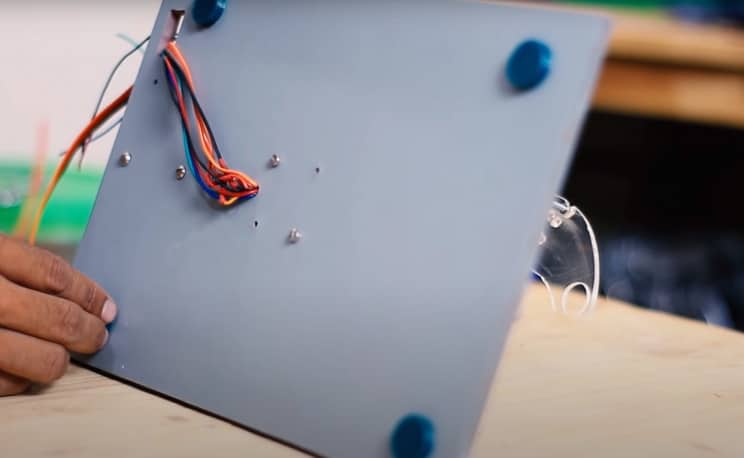
Next, take the MDF board and cut it to the same, or similar, dimensions as shown in the video. Mark out the position of screw holes of the servo motor, and other parts, in the same places as shown in the video. Now drill the holes, as required. With this stage complete, also spray or hand paint the board white (or any other color) and affix the 3D printed parts, as shown.
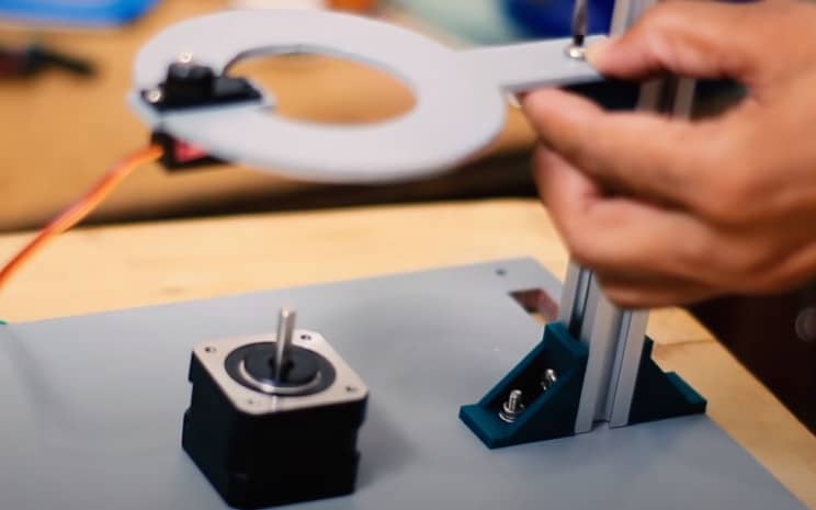
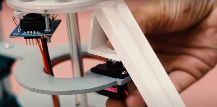
The next step is to take the aluminum profile piece, cut to the right length (if required), and affix to the MDF board between the plastic 3D printed brackets. The next stage is to create the lollipop-shaped micro-server holder using either 3D printing or hand cutting a piece of MDF. There are no instructions for this given so you will need to devise it yourself — it may take some trial and error. You may want to mock this piece up using cardboard prior to finalizing the design either cutting MDF to size or 3D printing.
Be sure to ensure the micro-server can fit snuggly and securely, as shown in the video (and below image). Insert the micro-server into the lollipop-shaped piece and the entire assembly to the profiled aluminum bar, as shown.
The next stage is to take the plexiglass and cut it to size and shape as shown in the instruction video. Attached this to the appropriate 3D printed bracket on the profiled aluminum bar. Again there are no instructions for this so it may take some trial and error.
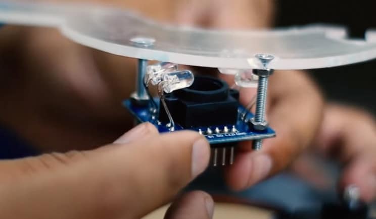
Now take the color sensor and wire up as instructed. Then affix to the plexiglass assembly, as shown above. Thread all wiring through the hole on the MDF base next to the stepper motor, and back up through the rectangular-shaped hole on the MDF board too. Affix four circular 3D printed pads (or similar) to the base of the MDF board to allow enough room for the wiring to run underneath the board.
The next stage is to thread the previously prepared aluminum rod onto the stepper motor in the center of the MDF board. Now screw the sorted disk onto the other free end of the assembly, as shown below.
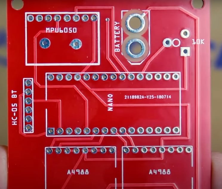
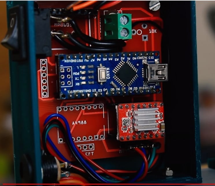
Next, create a custom PCB design Gerber file, as shown in the video (no file provided by the creator). You can use the services of companies like JLCPB to print it, or simply use a sandwich board for testing purposes.
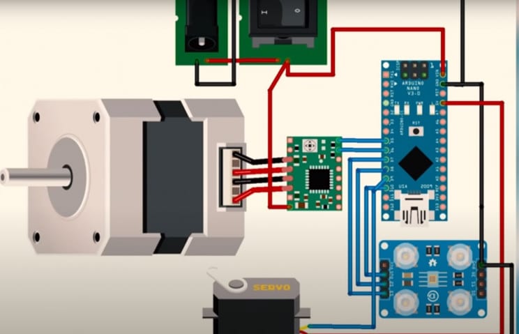
Now add the required PCB wire connectors, and solder, as shown in the video. Next, assemble the required components onto the circuit board, like the Arduino Nano, etc. The next step is one of the most important; the actual code. Here it is in its full glory. Feel free to play around with the parameters to your liking.
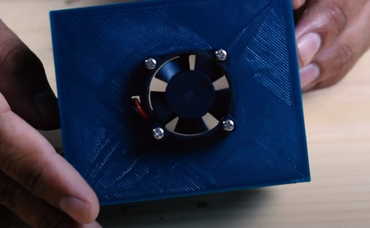
Once you are happy with the code, and it has compiled successfully, simply upload it to the Nano. The next step is to create the On/Off switch and main circuit housing. Take the 3D printed box and attach the micro fan as instructed.
Feed the wiring from the main color sorter assembly, and wire up/solder as required. Also, wire in the main On/Off switch and main power input assembly to the PCB board. See the video for details on this critical stage.
Next, add and hinge the box closer doors, as shown. You may need some small lengths of wire or cut a paperclip into appropriately sized lengths for this.
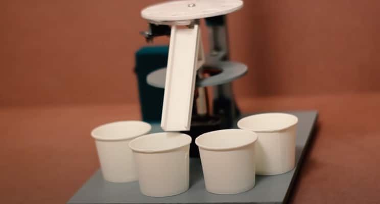
The next stage is to create the colored object sorting ramp. This will affix to the micro-server assembly. As no instructions are provided you might want to mock this piece up first in cardboard and either 3D print later or hand-make out of plastic-card or similar material.
Next, attach the ramp to the micro-servo. You can now place the four paper cups, or similar receptacles, arranged as shown in the video and below. These will receive the sorted colored objects from the ramp.
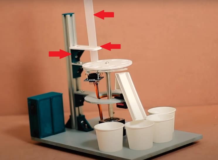
The next step is to cut a length of plastic tubing to the desired size to make the colored object hopper. This will need to have a slightly larger diameter to the colored objects, like Cadbury Gems, and receptacles on the sorting disk. Use the final 3D printed bracket to hold a supporting arm to the profiled aluminum rod and place the hopper tube in place above the disk. This will likely take some trial and error to get right (see the red arrows indicating the required parts below).
Now all that is left to do is to fill the hopper with your desired tablet candies, connect the power and fire it up. Watch in amazement as your carefully crafted Arduino code and machine work in perfect symphony to sort the candies into separate cups. Why not reward yourself by eating some, perhaps all, of them at your leisure!
