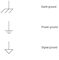
It should be stipulated to the point of prudence that the electrical and electronic symbols are identified so that your designed product is used to its full potential, correctly and is serviced safely as well. The terms “Earthing” and “Grounding” are interchangeably used, so it is very natural to confuse the two. We dissect the terms and symbols here for you today.
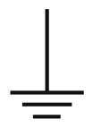
The “ground” symbol (Power Ground) to represent the net attached to a universal zero reference voltage, has always been a pile of three horizontal lines decreasing in length downwards. There is also now a symbol representing the open triangle pointing downwards (Signal Ground) as well as a symbol with what looks like a leaf sweeper, a horizontal line with three diagonally placed lines, relatively downwards (Earth Ground). The Earth Ground representing the connection to the earth in places like water pipes and represents the conduction of lightning safely to the ground.

Earlier it was commonly used in schematics of radio transmission as well, as a means to neutralize the antenna circuitry. Lower frequencies used at the time could use the earth connections for efficient radio transmissions, however, for the Giga-Hertz frequencies used today, the ground wire will have enough inductance to make the grounding attempt meaningless. The small electrical fields around the antennas can be counterpoised using a metal inside the devices’ circuit boards. In the case of power wiring, the “earth ground” is still potent in safety connections, where a breaker or fuse can prevent the current to flow in primary wiring, away from the metallic part of the device in the event of a short circuit.
We refer to the international standards mentioned in IEC 60204 Safety of machinery – Electrical equipment of machines – Part 1, 2005. The sections that explain the symbols are also given for reference here.
4.4.2: Electromagnetic compatibility (EMC)
No. 5017 Earth (ground): To represent an earth (ground) terminal in general, in case more specific grounding symbols such as 5018 or 5019 are not used.

No. 5020 Frame or chassis: To defend equipment against conducted and radiated RF disturbance also called The “Earth Ground.”

No. 5018 Noiseless (clean) earth (ground): To locate a noiseless earth terminal, such as that of a specifically designed grounding system to prevent malfunction of the equipment, or to limit common mode disturbance.

8.2.6: Protective Conductor Connecting Points
No. 5019 Protective earth (ground): The protective conductor connects two points in appliances or parts, nothing more. The connecting points to be labeled Green and Yellow for distinct identification. The symbols are usually seen to identify the terminals intended for external conductor connections, or the earthing terminal, for prevention of shock.

The term “Gound” is used in America, while the term “Earth” is used in other English-speaking parts of the world.
Credits: Quora


In the USA, the distinction Numan makes above is made in the Code by use of the terms “grounding” (for normally dead parts) and “grounded” (for normally live parts. Thus a grounding conductor is the earth ground, and a grounded conductor is the “neutral”.
Earthing:
Earthing means connecting the dead part (it means the part which does not carries current under normal condition) to the earth for example electrical equipment’s frames, enclosures, supports etc.
Grounding
Grounding means connecting the live part (it means the part which carries current under normal condition) to the earth for example neutral of power transformer.