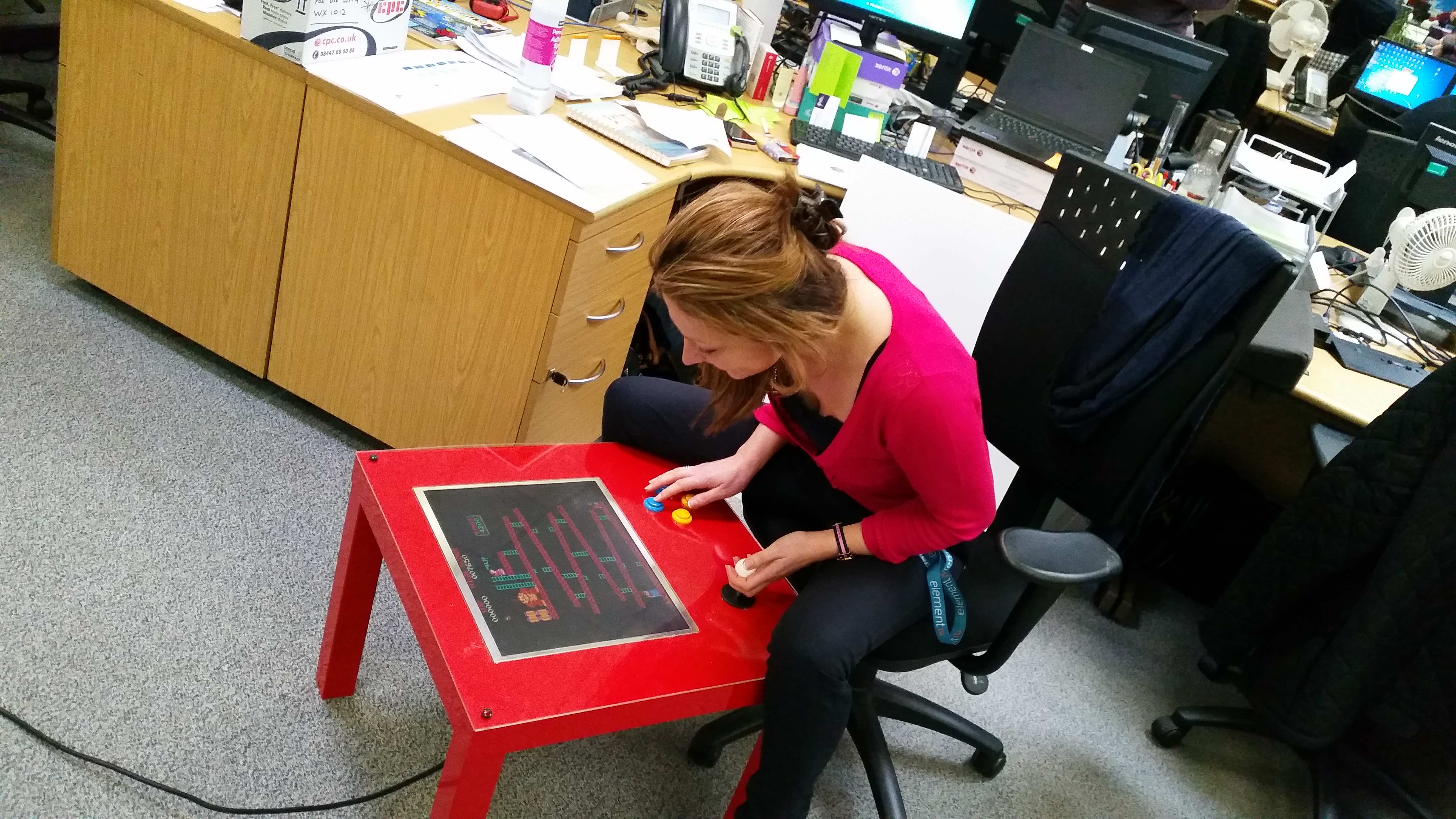
Are you bored with your plain old coffee table? Imagine a coffee table that you could play arcade games on. Now that would be a real game changer, quite literally, with the powerful combination of the two best things in this world, coffee and arcade game!
A hobbyist has given a retro treatment to the IKEA LACK table and the result is a mind-blowing yet reasonably priced arcade gaming layout.
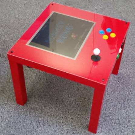
This minimalist design uses a Raspberry Pi 3 and an IKEA coffee table, hence the name PIK3A, to create this amazing retro arcade gaming platforms.
Materials
The blueprint of PIK3A gaming arcade table design requires the following parts:
- IKEA Lack coffee table
- Raspberry Pi
- Arduino Leonardo
- Four-way ball-top joystick
- Buttons
- 17-inches LCD monitor
- USB-powered computer speakers
- Raspberry Pi 2.5A USB power supply
- Wires and connectors
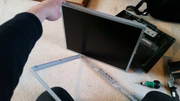
Step 1: Disassembling Your Monitor
Take a 17-inches LCD screen and remove the plastic chassis inside which it is encased. The screen sans casing will match the depth offered by the LACK IKEA coffee table, implying that it will be even with the surface of the table.
Step 2: Mounting the LCD Screen
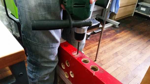
You can either use a hand-held power tool or opt for a simple utility knife because these tables work equally well with both. Trace the outline of the screen on the table to and ascertain the right size of the hole to fit the screen inside. Drill holes of 13 mm each in all the corners.
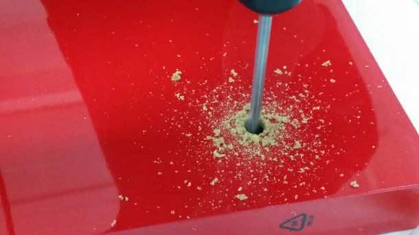
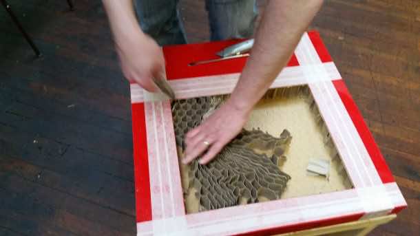
Start cutting the hole along the line, stopping about 10cm shy of the drilled holes. Cut along all the four traced sides and pull off the severed top. Be cautious while pulling out the cut-off part of the table top as it is held together by honeycomb paper filling inside which can be removed by running a sharp edge over and around it.
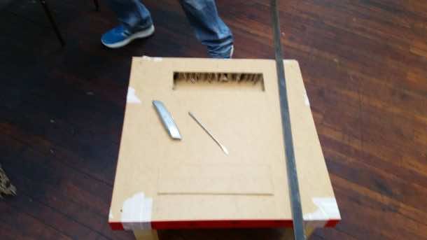
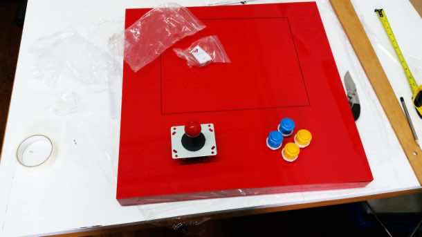
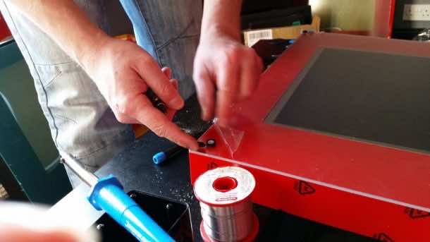
Step 3: Mounting the Control Module
Turn the table top upside down and cut an access panel to gain access to the back side so as to fit joystick and buttons. Mark the installation site for the joystick and the buttons and make 28mm (the standard arcade size for buttons) holes for each.
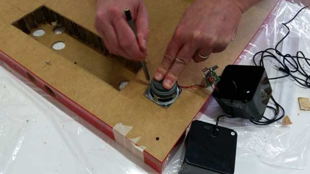
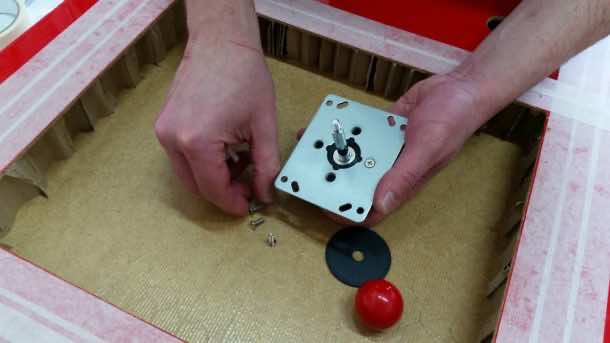
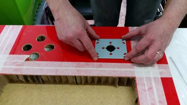
To give a seamless finish to the PIK3A, dismantle the mounting base of the joystick and insert the joystick from beneath the table. Once the joystick is in its right position, re-attach the mounting plate using the screws threaded via the table top. Buttons are much easier to place; all you need is to drill a hole of 28mm and secure the button in its place with a nut.
Step 4: Designing the Control Interface
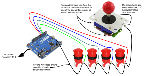
The arcade controls, including the joysticks, are quite simple. Since Raspberry Pi has been designed for a more sophisticated control, an Arduino Leonardo, acting as a standard keyboard, has been utilized to connect the arcade buttons with the Raspberry Pi.
Accordingly, each button of the PIK3A interface is connected to a Leonardo input. The Arduino board interprets the each button into a key press. The standard keyboard controls for MAME are employed. The sketch file given here enables the Arduino to translate the motion of the joystick as well as the button press actions, with MAME being used as a standard.
//element14 PIK3A Gaming Table Controls, using an Arduino Leonardo//
02.
03.void setup() {
04. Keyboard.begin();
05.
06.
07. //Joystick and buttons pin allocations
08. pinMode(0, INPUT_PULLUP); //Joystick Up
09. pinMode(1, INPUT_PULLUP); //Joystick Down
10. pinMode(2, INPUT_PULLUP); //Joystick Left
11. pinMode(3, INPUT_PULLUP); //Joystick Right
12. pinMode(4, INPUT_PULLUP); //Button 1
13. pinMode(5, INPUT_PULLUP); //Button 2
14. pinMode(6, INPUT_PULLUP); //Button 3
15. pinMode(7, INPUT_PULLUP); //Button 4
16. pinMode(8, INPUT_PULLUP); //Coin
17. pinMode(9, INPUT_PULLUP); //Start
18.}
19.
20.
21.void loop() {
22.
23.
24. // Button labels:
25. int joystickUp = digitalRead(0);
26. int joystickDown = digitalRead(1);
27. int joystickLeft = digitalRead(2);
28. int joystickRight = digitalRead(3);
29. int button1 = digitalRead(4);
30. int button2 = digitalRead(5);
31. int button3 = digitalRead(6);
32. int button4 = digitalRead(7);
33. int coin = digitalRead(8);
34. int start = digitalRead(9);
35.
36.
37. // Joystick Up – Arrow Up Key
38. if (joystickUp == LOW) {
39. Keyboard.press(218);
40. }
41. else {
42. Keyboard.release(218);
43. }
44.
45.
46. // Joystick Down – Arrow Down Key
47. if (joystickDown == LOW) {
48. Keyboard.press(217);
49. }
50. else {
51. Keyboard.release(217);
52. }
53.
54.
55. // Joystick Left – Arrow Left Key
56. if (joystickLeft == LOW) {
57. Keyboard.press(216);
58. }
59. else {
60. Keyboard.release(216);
61. }
62.
63.
64. // Joystick Right – Arrow Right Key
65. if (joystickRight == LOW) {
66. Keyboard.press(215);
67. }
68. else {
69. Keyboard.release(215);
70. }
71.
72.
73. // Button 1 – Left CTRL
74. if (button1 == LOW) {
75. Keyboard.press(128);
76. }
77. else {
78. Keyboard.release(128);
79. }
80.
81.
82. // Button 2 – Left ALT
83. if (button2 == LOW) {
84. Keyboard.press(130);
85. }
86. else {
87. Keyboard.release(130);
88. }
89.
90.
91. // Button 3 – Left CTRL
92. if (button3 == LOW) {
93. Keyboard.press(32);
94. }
95. else {
96. Keyboard.release(32);
97. }
98.
99.
100. // Button 4 – Left CTRL
101. if (button4 == LOW) {
102. Keyboard.press(129);
103. }
104. else {
105. Keyboard.release(129);
106. }
107.
108.
109. // Coin – 5
110. if (coin == LOW) {
111. Keyboard.press(53);
112. }
113. else {
114. Keyboard.release(53);
115. }
116.
117.
118. // Start – 1
119. if (start == LOW) {
120. Keyboard.press(49); delay(100);
121. }
122. else {
123. Keyboard.release(49);
124. }
125.
126.}
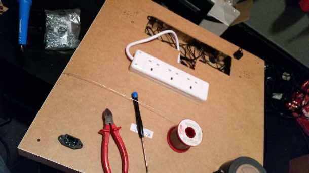
Step 5: Connecting the Audio system
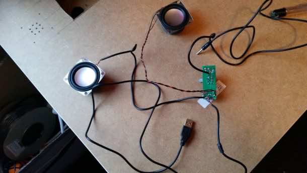
The USB speakers are best suited for this PIK3A arcade gaming table. Opt for the externally-powered USB speakers to enjoy an enhanced audio experience. Attach the USB speakers in the downward direction inside the table to make certain that the grille holes remain hidden. Insert the 3.5mm audio jack into Raspberry Pi input.
A volume control board is mounted on the table by drilling holes of 10mm and securing it in its placing using the hot glue.
Step 6: Power Module
Since the space inside the table will run out very fast, it is best to install a connector underneath the table and plug in an extension lead.
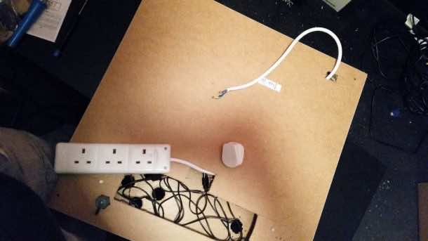
Albeit the speakers and the Raspberry Pi modules are being powered separately, the speakers can also be powered through the Pi3 USB ports.
Step 7: The Final Touch
Since the removal of the shielding case of the LCD makes it prone to accidents, therefore it is highly recommended to cover the panel using a 3mm acrylic screen to sit on the top of the screen.
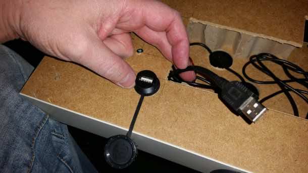
You can also consider adding a USB port to the access panel to ensure that your PIK3A gaming table will also be compatible with the USB plug-in keyboard.
Delve into the world of arcade gaming with this cool PIK3A project to transform an IKEA coffee table into an incredible arcade experience.
